Boundary Interactions
|
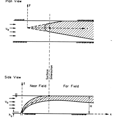
Boundary interaction occurs when the flow contacts the surface, bottom, or forms a terminal layer in
a density-stratified ambient environment.
Boundary interaction also determines if mixing is controlled by stable or unstable
discharge source conditions.
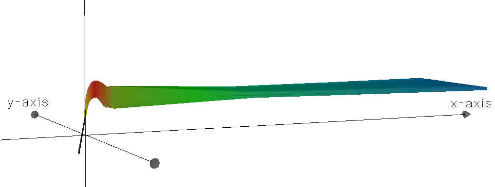
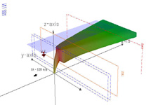
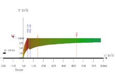
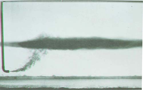
Boundary interaction generally provides the transition from near-field (discharge source controlled)
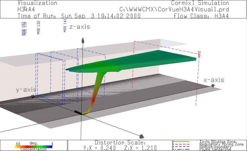
to far-field (ambient controlled) mixing processes as illustrated by the image on the right.
However, boundary interaction in the form of dynamic plume attachments to the bottom are
considered near-field mixing processes.
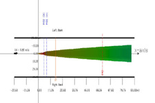
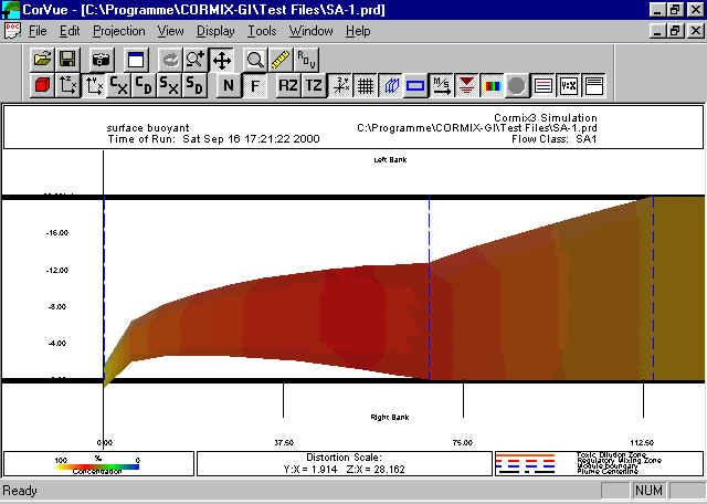
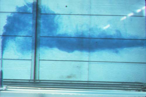
After surface boundary interadtion occurs, this plume shows lateral shoreline boundary interaction.
|
A CorVue visualization of lateral boundary interaction.
|
Dynamic flow attachments occur when the discharge interacts strongly with a boundary
in the near-field.
These near-field boundary interactions present the possibility of high pollutant concentrations and undesirable benthic impacts.
These flows can also exhibit subsequent buoyant lift-off or drop-off with an unstable near-field.
Attachments are indicated by the CORMIX (..) An flow class suffix
in the CORMIX flow classification , which also describes dynamic attachment mechanisms and lift-off/drop-off conditions.
The image on the right shows a LIF image of a laboratory experiment with near-field dynamic flow attachment.
Often these near-field attachments are avoidable with proper outfall design facilitated by
the CorVue, CorSpy, and CorSens
advanced analysis tools.
|
Wake attachment in the near-field .
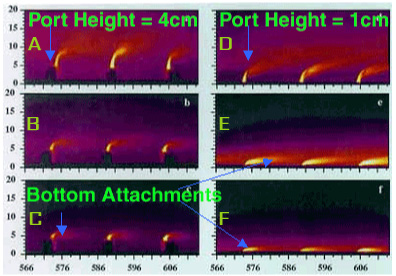
This set of false-color laser-induced fluorescence images illustrates boundary interaction behavior for a multiport diffuser
in crossflow. Crossflow velocity (left to right) is increased from top series (a, d) to the bottom (c, f)
causing plume wake attachment (c, e, f).
The greater discharge port height on the left (a, b, c) resists bottom attachment as crossflow
velocity increases. Wake attachment is indicated by a CORMIX (..) A2 flow classification,
and can have undesirable and avoidable benthic ecological impacts (Photo: S. Monismith).
|
CORMIX Boundary Interaction / Discharge Stability
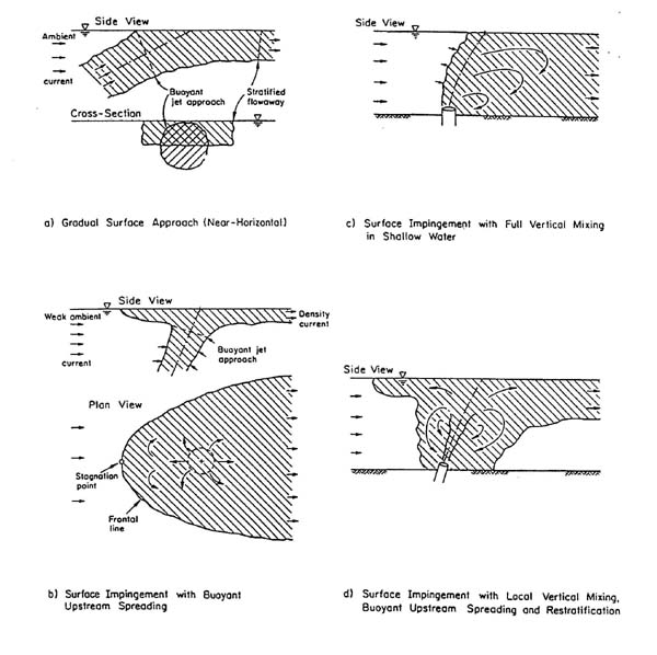
Examples of the four types of boundary interaction modeled by CORMIX appear in the image on the right.
The analyst can use CorVue to visualize these boundary interaction
processes in relationship to regulatory mixing zones. In CORMIX, mixing conditions at the impingement
point can take on one of the following 4 types:
- A turbulent buoyant jet is bent-over by a cross-flow, it will gradually approach the surface, bottom or terminal level and will undergo a smooth, stable transition with little additional mixing (Image a). However, a jet impinging normally, or near-normally, on a boundary will rapidly spread in all directions.
- The flow has sufficient buoyancy and ultimately forms a stable layer at the surface (Image b). In the presence of weak ambient flow this will lead to a density current upstream intrusion and stagnation point against the ambient current.
- The buoyancy of the flow is weak or its momentum very high, unstable recirculation phenomena can occur in the discharge vicinity (Image c). This local recirculation leads to re-entrainment of already mixed water back into the buoyant jet region.
- The intermediate case; a combination of unstable localized vertical mixing and density current upstream spreading with a stagnation point may result (Image d).
|
|
Laboratories Images of Boundary Interaction / Discharge Stability
|
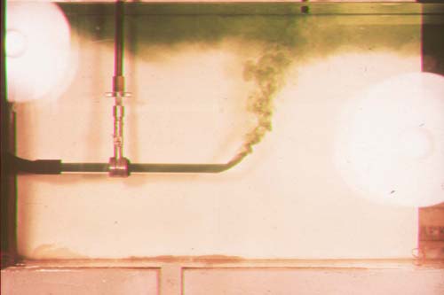
Ambient density stratification causes boundary interaction in the form of terminal level formation
(Image Source: Hofer, Kurt (1978) - Eine verbesserte Theorie turbulenter Freistrahlen im stratifizierten Medium und ihr Vergleich mit dem Experiment.
Mitteilung VAW-ETH No. 31).
|
|
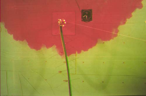
An upstream density current forms in this plan view. (Image: G. Jirka, DeFrees Hydraulics Lab) |
|
|
|
|
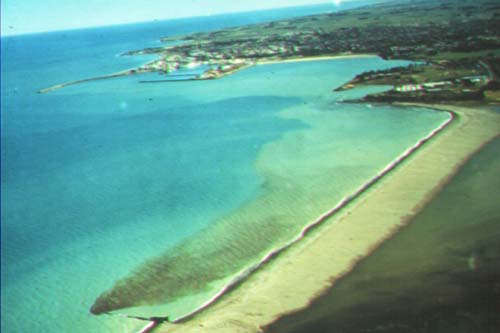
Field Images of Boundary Interaction / Discharge Stability
|
|
|
|
|
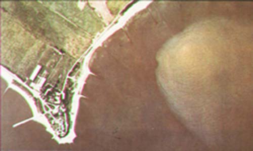
This near-shore discharge exhibits lateral boundary interaction. Photo: I. Wood, Univ. of Canterbury)
|
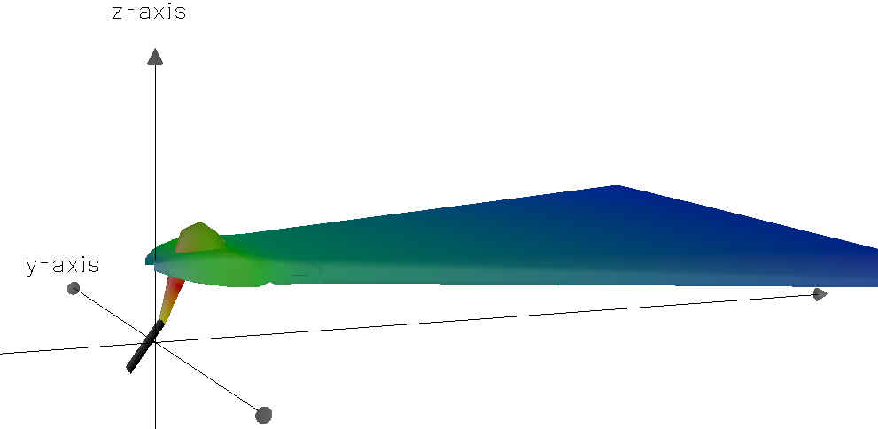
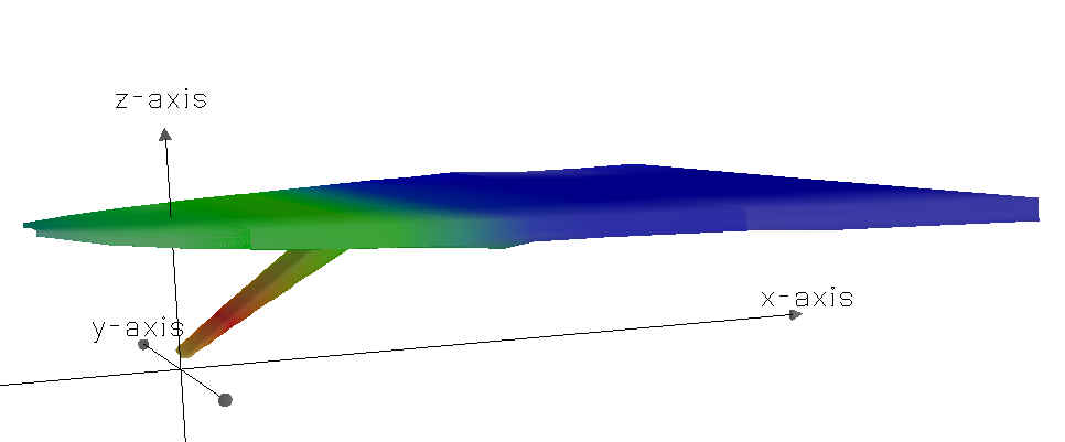
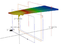
CorVue Visualizations of Boundary Interactions
|
|

l.jpg)
l.jpg)